Tuesday 16 March 2021

Setting LargeAddressAware in VisualStudio 2019

 Introduction

We write a lot of applications that use a 32bit dll, so we have to compile them as x86 builds. But they also load very large data files so we need to set the LargeAddressAware flag on the executable. While we were using .net Framework we used the LargeAddressAware nuget package and it worked great. This gets us over the 2Gb limit and ensures we don't get out of memory problems.

After starting to create .Net Core applications and we've found that this method no longer works. The setting of the LargeAddressFlag needs to be set on the executable, but the nuget package now applies this to the dll.

Setting the flag in Core

We're had to fall-back to creating our own post-build processing that uses the macros to build the location to the compiled executable. Here's how we did it:-

  1. Go to your project property settings and select the Build Events page.

  2. Enter the following code into the Post-build event command line.

call "$(DevEnvDir)..\tools\VsDevCmd.bat"
editbin /LARGEADDRESSAWARE "$(TargetDir)$(TargetName).exe"

The first line adds editbin to the path, and this is correct for Visual Studio 2019. At some stage this may need to be updated, and older versions of Visual Studio probably won't work.

LargeAddressAware added in Post-Build


Saturday 4 January 2020

Improving Telecaster Intonation

Introduction

Earlier this year I built a telecaster from parts and I tried my best to make it look traditional / vintage with my choice of parts. This meant using a three saddle bridge, which I knew was always going to be a compromise. The bridge I bought at the time was a cheap rip-off of a Gotoh modern style tele bridge, but with only the top loading option. Although it had been advertised as compensated, in practice I found it rather lacking.

Here's what the bridge looked like before I started..

The Original IOZ5 Steel Bridge
I didn't have a lot of choice due to the limitations of the body and routing, but this unbranded top-loader style bridge does the job. My intention had always been to upgrade the saddles at a later date.

Upgrade Time

Much of the electrics and hardware came from Northwest Guitars, I'm not endorsing them, they don't sponsor me, but they seem to be a good retailer for parts in the UK. I found they stocked just the thing I wanted, compensated brass saddles. They are essentially unbranded, low cost, and identical to Wilkinson Vintage Compensated saddles.

They arrived a few days later in a simple ziplock bag..

Compensated Brass Telecaster Saddles

They have been nicely machined, have shorter height screws and mounting bolts than those I have fitted, but the screw threads match perfectly. Also if you look closely you will see that one of the saddles is different to the other two. This surprised me at first (Northwests' photo showed them all the same), so I had to do a quick look on the web to see this was correct.

Odd one out goes in the middle!

The reason for this inconsistency is that the middle saddle caters for both a wound and unwound string. Northwest suggest if you are using a wound G then this middle saddle can be flipped over, but for now I'm going to assume the manufacturer knew what they were doing.

Fitting The Saddles

Installation was simply a case of loosening each pair of strings, marking the approximate saddle location with a bit of masking tape and then swapping them out. Even if you take your time, you'll be done in 10 minutes. (remembering the odd one goes in the middle)

Compensated Saddles Fitted
Then it was just a case of getting my tuner out and re-setting the intonation. You soon start to see the two diagonal lines pattern you expect to see on a bridge and I've gotta say, with these new saddles fitted, you really can get intonation close to perfect.

It's amazing how much better a guitar sounds when it's in tune as you go up the neck.

An additional benefit with the shorter height screws is that they don't poke up so high, nor are they as sharp as the previous ones. All-in it's a cheap and very positive improvement to my guitar.

Wednesday 16 October 2019

Building A Partscaster (Telecaster) Part 7 - Finishing Off

Introduction

With the wiring mostly done, the last stage was to add my chosen pickups, get the control plate mounted and fasten down the scratch guard. These should have been easy tasks, but that non-standard body was continuing to threw spanners in the works.

The control plate was overlapping one of the pickguard screws.

The Route to Success

After some thought, I took the decision to alter the body, as it's already been modified and repaired at the bridge routing. The control cavity would have to be widened on one side, but not having many woodwork tools, I wondered how best to do this. (chisel, Dremel with circular blade, drill loads of holes?)

I was sure most of the methods I had available to me would look terrible, so I ordered a cheap mini-router from eBay and a selection of router bits.

My new Katsu mini router
This isn't a review of the router, although I will say after a little practise on some scrap wood I was very happy with the results. I measured the gap from the edge of the router to where the cut was made and this gave me my offset.

Next I clamped a wooden guide onto the guitar body using this offset and a line I'd made on some masking tape to mark the new cavity edge. All I needed to do now was set the router depth, hold my breath and start cutting.

The body ready for routing
I had to do two cuts at different depths because the cutting tool wasn't deep enough, but this reduced load on the router and gave me more control. I took my time, being careful to avoid burn marks and to freehand the curved ends.

The completed routing (the black line marks the edge of the plate).
I also cleaned up where the cavity had been chiseled out to give the switch more space. There's not a lot of wood depth here, so I removed very little. I had to unsolder and pull the ground wires back before I started, and here you can see I've re-attached one of them.


The pick guard stills needs modification.
With the control cavity done, attention turned to the pick guard. The extended cavity now lines up better with the pick guard cutout, but it still needs modifying a little. I drew round the control plate with a marker pen and then used a rotatory file on my electric drill to rough it out.


The pick guard modification completed.

I finished off with a fine half-round file and re-checked that everything fitted well. The screw holes were then marked and drilled with a 2mm bit.


The copper shielding in place. (notice twisted pickup wires to reduce hum)

The body had been shielded with copper tape, so before finishing the electrical work, I replaced this with gardeners anti-slug copper tape. This stuff is quite cheap, I just cut off the serrated edges or trimmed down as required. I then applied a little plumbers flux to the stuck down edges and soldered all the pieces together. (They need to form one continuous cover)

The pickup mounting springs were replaced with neoprene tubing, and I found that a little bit of lubrication helped them fit over the pickup mounting bolts. It's a common modification that removes microphonic pickup noise, but I figured it was better to do it now. Then it was onto the socket.


Modern screw fitted output jack.
I'd read that you need a special tool to fit telecaster socket mounts, and while I liked the idea of being authentic, it sounded like a load of hassle. Most people seemed to be removing them and fitting these screw mounted sockets that don't go loose or wobbly. So that's another upgrade pre-fitted.

The final step was to solder the pickups and output jack onto the pre-wired control plate and ensure all ground connections were made properly. Screwing things back together before testing is tempting fate, so I plugged it into my THR5 amp and checked the wiring before buttoning it all up. To my surprise everything worked, those Seymour Duncan wiring diagrams were spot on.

The completed guitar body.
And here is the finished guitar, ready to be set up and played. Initial tests revealed a very trebly sound which was easily tamed by backing off the tone control. The series switch mode (in position four) had bags of volume and then the phase switch on the tone-pull really thins-out the sound.

I like it.


Sunday 13 October 2019

Building A Partscaster (Telecaster) Part 6 - Pickups

Introduction

The basic guitar is now working in an acoustic way and the control wiring is done, so it's time to move onto the pickups. There are a few design elements that create the "telecaster" sound, but the most important thing is the pickups. They have evolved throughout the years from Leo's original lapsteel pickup, to the modern noiseless pickups that are voiced to sound like they've come from the 1960's.

Ideally I'm aiming for a 1950's sound, but as I started researching, I became bombarded with specs that don't match up to what's readily available today. In fact, the more I looked into it, the more a minefield choosing pickups became. But what's so special about telecaster pickups?

Pickup History

The thing that's quite obvious on a Telecaster, is how unique the pickups are. There's that large pickup built into the bridge, paired with a smaller chrome covered neck pickup, which reminds me of the dissimilar size wheels on a chopper.

Telecaster Pickups.

The original tele was called the Esquire and it only had the bridge pickup. Leo's design used a copper or zinc plated steel base plate with alnico pole pieces and had a relatively low output compared to today's pickups.

The Fender Esquire Pickup

Bolting this directly into the steel bridge focused the magnetic field in a way that made the sound brighter. In fact the resulting sound was too bright and the guitar relied on a series of switched capacitor circuits to tame the harsh trebly tone. Together with its lack of truss rod, (which saw many of the first batch of guitars returned due to bent necks) showed this design to be little more than a stepping stone along the way.
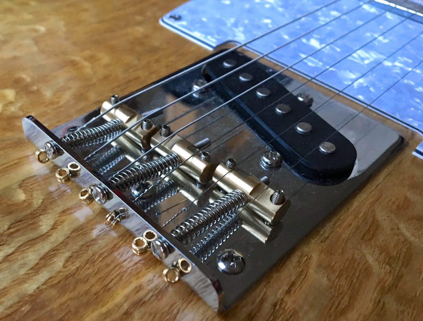
The Bridge Pickup

The bridge pickup isn't too unusual at first glance, but there are two important differences. First it has that steel base plate, and secondly it uses the bridge as an integral part of its magnetic field.

Left bridge pickup, right comparison of magnetic fields.
Compare the bottom field diagram from a telecaster with the one above from a stratocaster. The concentration is clearly stronger, while the pole piece magnets themselves are about the same strength.

The Telecaster neck pickup started out with 43AWG enamelled wire (with a 10kΩ resistance) and soon switched to thicker 42AWG wire (with a 7.8kΩ resistance). They initially had alnico III pole piece magnets, but this was later changed to alnico V and the windings reduced to around 6 to 7kΩ. Standards were pretty loose back then, so windings on the coils could vary by hundreds of turns, and the pole pieces themselves weren't always guaranteed to be Alnico V spec.

The Neck Pickup

The neck pickup was added to the later broadcaster and subsequent guitars, and uses a smaller narrow coil with a metal covering. Typically the neck pickup is as described as "dark" sounding, while the bridge pickup is "bright", and this leads to good mix when the two are used together. The cover itself darkens the sound and it can be removed to open the sound up a bit, to the detriment of increased hum.

It's hard to say much else about this really. It's not uncommon for guitar players to swap out the neck pickup because they're pretty uninspiring, but as I've got no experience with them, my plan was just to get something typically telecaster and see how I felt about them.

What To Buy?

The more research I made, the more variation there seemed to be in Telecaster pickups. In those first few years of the 50's they changed so much, and then there was the changes into the CBS era. I read a lot of reviews, watched a lot of demos and still failed to make a buying decision. It didn't want anything 'hot', expensive, or particularly special in any way. But I had little to go on, other than I wanted alnico magnets rather than ceramic, and low output levels.

I nearly went for Tonerider Hot Classics, the price was reasonable and they sounded okay, but like most of the premium brands, they seemed to only offer slightly hotter versions.

In the end, I spent a very modest £17 on some unbranded alnico V pickups with coil resistances in the right ball park. I'm not a great believer in hype and it's unlikely I'll see any difference to the more expensive pickup sets with similar specifications (which I have no experience of anyway).

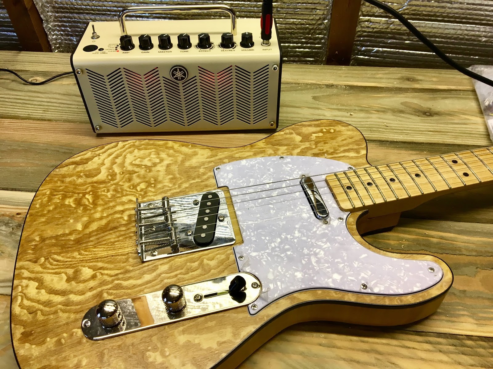
Cheap Alnico V pickups from eBay

So, here's what I bought, something not far from the 1955 spec, which should be bright and twangy. My plan is, they'll do for now and can always be swapped out later if I don't like them.

Thursday 3 October 2019

Building A Partscaster (Telecaster) Part 5 - Wiring

Introduction

We mostly think of guitars with two pickups just needing a three selector switch. Be it the Gibson style toggle, or the Fender lever style. But while researching wiring circuits I came across Fenders Baja wiring which uses a four position switch and Fender's S1 Switch. This intrieged me so much that I decided it was worth the slight increase in the cost.

Choosing Parts

Yeah we're back here again, but this time we've got all the tricky decisions sorted. It's simply a case of getting the following parts:-
  • Pots
  • 4-Way Switch
  • Socket
  • Tone Capacitor
  • Phase Switch
  • Wire

Pots

Fender uses CTX potentiometers, but you can save a little bit of money going for the CTX brand directly, rather than the ones available from Fender.

But, if you go for Alpha pots, these are comparable size and quality and about half the price, but the main advice I read seemed to be, "stay clear of unbranded or mini pots"

CTX pot with split shaft, Alpha pot with solid shaft and push-pull Alpha pot.

The other thing to be aware of is that they come in linear or audio taper tracks. Most guitars use the audio type.

You also need to consider whether to buy solid or split shaft. This normally depends on the type of knobs you intend to use.

4-Way Switch

You will basically find two types of lever switch, especially on eBay. There's the high quality Oak Grigsby style, or the cheaper circuit board type. They'll both do the job, but the O-G type will last longer than the other.

The two types of switches available, left Oak Grigsby, right circuit board type.
It's also worth considering the Oak Grigsby style has open wafers which can be more easily cleaned.

Socket

Your choice is similar to the switch, you can get a heavy duty Switchcraft style switch which can be easily cleaned, or a moulded plastic type. You need to be aware that there are metric and imperial threads, so ensure they match the jack plate you intend to use.

Tone Capacitor

And now we come to contentious bit... a lot of people will swear that for the best tone, you have to use a Paper-in-Oil (PIO) capacitors. Others will use "Orange Drops" which are polyester, and some say old "Bumble Bee" capacitors are the best, which are a PIO type often advertised as giving a "Woman Tone". You can pay silly money for these, and the truth is they won't sound any different to a polyester type, it's just another one of those myths.

You can in fact use any type, although I've heard that ceramic disk type can be microphonic, so are best avoided. You still see them in cheap guitars though. What ever's practical and convenient.

My advice here is to buy the correct value, (0.047uf for Fender single coil) and if you get them from an electronics supplier you can get them for a third of the price. (I bought a pack of ten for £1.35)

Phase Switch

If money's no object then you can pick up an S1 switch from fender. Any double-pole, double-throw switch will do the job, so it's down to preference. I went with the push-pull alpha pot so it's built into my tone control.

Wire

Some will say it has to be the vintage cotton covered hookup wire. But the truth is, it makes no difference to cheaper PVC wire. I suppose it's another one of those personal preferences, you either want to go fully vintage with a PIO cap, or you accept nobody's going to see it and just buy what works well.

My Completed Control Panel

Here's my completed panel, I based it on a wiring diagram I downloaded from Seymour Duncan. I altered this slightly by using my phase switch on the bridge pickup. You also need to run a separate ground wire from each of the pickups.

The Baja wired control plate using a 4 way switch and a switch tone pot.
You should also run your grounds in a star configuration, avoiding any loops (which will introduce hum). For instance, if you have two separately grounded parts, don't touch them together.

Thursday 19 September 2019

Building A Partscaster (Telecaster) Part 4 - The Bridge

Introduction

If you remember back in my first post, I mentioned the bridge pickup routing had been enlarged. I was hoping that the bridge I bought would cover it (and it does), but one thing that was really bothering me was that it seemed to be in the wrong place.

Comparing dimensions (Fender on the left)
I hadn't noticed before how the shape of the body differed from the Fender shape. Not only is it wider at the bottom, but the top left is less pronounced. The control routing is slightly higher, and you can see from the blue line that the bridge positioning is wrong.

This is probably going to make tuning and intonation impossible.

A Closer View

I was a bit annoyed, so I messaged the vendor on Ebay. He sent me photos of the old bridge he'd taken off it, and it seemed to match the one I'd bought. Maybe it will work, but until the neck had arrived I didn't know for sure.

The photo from the vendor

My bridge has the same dimensions and those mounting holes match exactly.

My bridge showing the measurement from the nut.
A few days later, the neck arrived and it became clear (with a neck scale of 25½ inches) that those saddles won't go back far enough. It might have had a shorter scale neck before, or maybe it was gooched and this explains why the donor guitar had been stripped for parts.

Not a huge problem you might say, just drill new holes and mount it in the right place?

Yeah, but that will uncover that ugly botched hole!!

Filling the Hole

There was no choice if I wanted it to work properly, the bridge has to be in the right place and I needed to replace the missing wood from the body. Here's the steps I took:-
  1. Make a paper template.
  2. Glue template onto pine block (soft wood is easier to work with).
  3. Cut out and sand into a close fitting shape.
  4. Remove copper foil from the hole and glue block in with PVA.
  5. Repeat with a piece of thin ply with a similar grain to the body veneer.
  6. Stain a golden colour (I used a mix of coriander and tea).
  7. Apply four coats of varnish.
Left the completed body repair, right with bridge and pickguard fitted.

Okay it's not great, the resulting colour isn't quite right, but once the bridge and pickguard are fitted, most of it is hidden. In fact you have to look quite closely to notice it.

Fitting the Bridge

I used the "fit the two E strings" method to position the bridge, ensuring the strings sat in the right nut slots. I pulled the strings tight, ensuring the gap to the fret board edges is the same both sides and the bridge was square. It took me a few attempts before I was happy, so if you're doing this, double check before you start drilling holes.

Once that was done, I couldn't resist throwing some strings on and trying it out.

Sunday 15 September 2019

Building A Partscaster (Telecaster) Part 3 - Fitting the Neck

Introduction

I've got to say, choosing the parts for the build has been quite a challenge. After ordering a 1951 style neck, I decided it would be good to try and get hardware to match. I'd already bought a 97mm standard bridge to cover that enlarged pickup routing, so it wasn't going to have the traditional ashtray style. I does at least have just three saddles. But now I was starting to be concerned that it wasn't going to work, but more about that at a later date. Here's a photo of most of the parts, before I started building.

I've been busy on Ebay

Mounting the Tuners

I really like the idea of split shafts on the Kluson tuners. The guitar string goes down the hole in the middle, so there's no sharp end waiting to spike you. But what I thought would be a simple job, became complicated.

The vintage Fender neck is supposed to have 9mm tuner holes. The Kluson's are a simple pressed steel design, authentic for this era, but the press-in bushes were too loose. The holes in the neck were actually 9.4mm with the bushes being 8.6mm, so I was a little confused as to whether I'd bought a 9mm neck or a modern style 10mm one. I could pay £10 for the 10mm bushes, but that felt like a lot to pay, I'd then still have to open the holes a little, and I'd have to delay the project.

In the end, I painted the inside of the holes with varnish (about 5 coats) until they fit snuggly.

Fitting The Neck

If you buy a non-fender body, the specs may not be standard, and in my case this was definitely true. In my case the over-all shape is slightly different, and the neck was loose in the neck pocket. If left like this I would always have re-alignment problems whenever I took the neck off.

The solution is simple enough, I glued a piece of veneer to the bottom side of the pocket.

A small piece of veneer makes the fit snug.
The neck was a tight fit now so I grabbed the neck plate and bolted the neck on. Having the holes pre-drilled was great (thanks Fender), finally something easy.

The neck fitted and complete.

I now had something that looked like a guitar, and the next step is fitting that bridge. It turned out to be a problem, so I'll cover that in the next blog.

Thanks for reading.